|
Next thing to check is rverse clutch
pack clearance. There is a small opening in the case (toward
the rear of the main case) that looks like a window). You
can see the reverse clutches through the opening. Use a set
of feeler gauges and try different combinations until it
is a snug fit between one of the steels and a friction. Write
down this clearance, as you will need it later.
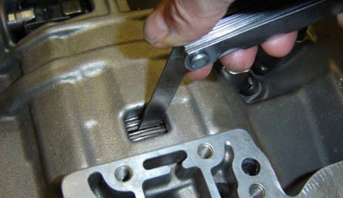 This photo shows the “window” you can
use to access the reverse clutches. Just spread one clutch
and steel and stack up enough feeler gauges until it is a
snug fit. Write down this clearance, we shoot for .075” to
.100”.
This photo shows the “window” you can
use to access the reverse clutches. Just spread one clutch
and steel and stack up enough feeler gauges until it is a
snug fit. Write down this clearance, we shoot for .075” to
.100”.
The removal of the front pump is next. Remove the seven
bolts that retain the front pump. Use the slide hammer and
work the pump out with some care. Yanking on it or prying
on it will nick up the machined area on the case and cause
a leak later. Take your time, it will be worth it. Once the
front pump is out I recommend focusing on it for a while.
Clean up a separate area and take the five bolts out that
hold the two halves together. When it comes apart there are
some inspections to do and some modifications to make.
Front pump: I have not looked at hundreds of front pumps
like some rebuilders have but so far I have seen a lot of
variation in oil hole diameters and a definite need to improve
them all.
- Inspect
the stator support tube. If the splines that the converter
slides over look good and it is not cracked where it is pressed
into the pump housing it should be OK. There are aftermarket
stator supports available made from 4340 steel that are bushed
to support the common turbo-spline input shaft. Not a bad
investment in durability for about $60.00.
- While
it is apart is look closely at the pump gears and the
surfaces they ride on. If the gears look good and have
no pitting or flaking they are likely OK to use again.
If the pump housing has scratches or grooves worn into
it that can catch your fingernail you need to replace the
pump side and the gears. If the stator support side has
grooves that deep you can replace it or have it machined
flat. We machined our own since Andy is a Tool & Die
Maker but the cost would be about $30-45 in a machine shop.
- Pump
housing to gear clearances are important for reliable pressure.
The clearance between the driven gear (larger one) outer
surface and the pump housing should be .0035” to .0065”.
If you have too much clearance the pump housing should be
replaced. The other thing to measure is the inner diameter
of the driven gear to the pump “crescent” clearance.
This should be .003” to .009”. One last thing
to check is the clearance of the gears to the pump body.
Take a straightedge, lay it across the gears and housing,
there should be .0005” to .0015”. Gears and pump
bodies that don’t meet those specs should be replaced.
Oversize gear sets are available, check with your transmission
parts supplier.
- With
the stator support facing up you will see a small hole
next to the tube. It should be ¼” in diameter. If
it is not, get a long ¼” drill bit and drill
it out until it intersects with the hole in the pump body.
That hole should also be ¼”. This is the converter
charge (fill) circuit and is important to consistent and
maximum efficiency of the torque converter. There is a small
hole on the other half of the front pump. It is the oil feed
hole for the pump to high gear bushing. I enlarge this hole
to .095” to increase oil supply to the bushing (or
Torrington bearing if so equipped). CAUTION: This hole needs
to be drilled into the housing about 3/8” of an inch.
DO NOT drill clear through the housing.
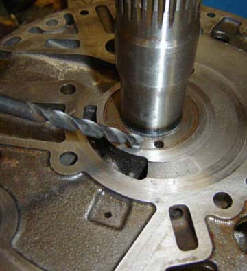 |
This picture shows a couple things. First is the condition
of this side of the pump where the gears run. It is free
of deep scratches and can be used again. The second is
the converter feed hole. In this pump it was smaller
than the preferred .250”. It takes a 6” long
bit so you can drill it straight but it is a simple operation.
Drill it until it intersects with adjoining passage. |
|